

The interaction curve is a complete graphical representation of the design strength of a uniaxially eccentrically loaded column of given proportions. Each point on the curve corresponds to the design strength values of PuR and MuR associated with a specific eccentricity (e) of loading. The interaction curve defines the different (MuR, PuR) combinations for all possible eccentricities of loading 0 ≤ e < ∞. For design purposes, the calculations of MuR and PuR are based on the design stress-strain curves (including the partial safety factors), and the resulting interaction curve is sometimes referred to as the design interaction curve (which is different from the characteristic interaction curve).
In other words, the design interaction curve serves as a failure envelope. Of course, it must be appreciated that by the term safe , all that is implied is that the risk of failure is deemed by the Code to be acceptably low. It does not follow (as some designers are inclined to believe), that if the point (Mu, Pu) falls outside the failure envelope, the column will fail!
The salient points, marked 1 to 5 on the interaction curve [Fig. 1.1] correspond to the failure strain profiles, marked 1 to 5
In this section, the detailed calculations for determining the design strength of a uniaxially eccentrically loaded column with a rectangular cross-section (b × D) is described in detail. The notation D denotes the ‘depth’ of the rectangular section in the plane of bending, i.e., either Dx or Dy, depending on whether bending occurs with respect to the major axis or minor axis, and the notation b denotes the breadth (width) of the section (in the perpendicular direction). The basic procedure for other cross-sectional shapes (including circular sections) is similar.
Generalised expressions for the resultant force in concrete (Cc) as well as its moment (Mc) with respect to the centroidal axis of bending may be derived as follows, based on Fig. 1.2
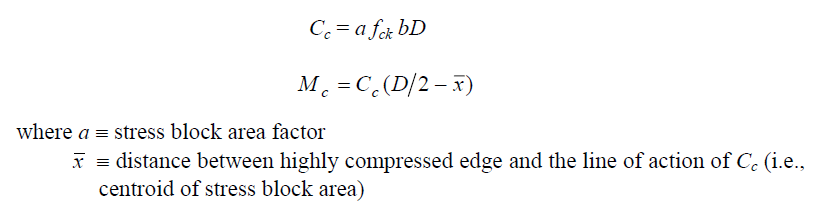
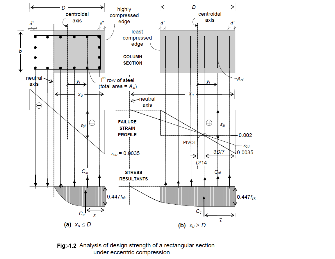
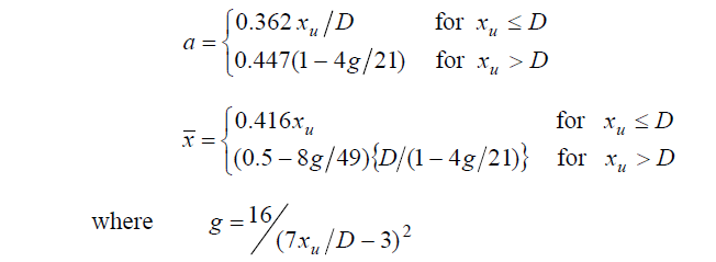
By means of simple integration, it is possible to derive expression for a and x for the case (a): xu ≤ D and for the case (b): xu > D
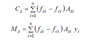
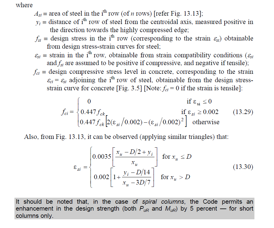
Similarly, the expressions for the resultant force in the steel (Cs) as well as its moment (Ms) with respect to the centroidal axis of bending is easily obtained as:
Prepared By Shiv Nath Mishra